electronics:thermoprinter
Table of Contents
Thermoprinter
General info
Here I will post the information and progress about my diploma thesis. Shortly describing the project, it should be portable thermoprinter with bluetooth/USB communication, supporting multiple protocols.
This type of printer can be used with POS for printing recipes or with scientific equipment for printing reports.
Assets
What I have:
- Thermoprinter head
- STM32-Nucleo eval board
- BLE module
- All needed connectors that fit thermoprinter head
Stepper motor driver breakout module- Li-Ion batteries and holders
- Li-Ion battery protection and charging circuits
- Other small parts, like voltage regulators, LEDs, buttons, descreet elements
What is missing:
Some transistorsProper stepper motor driver IC- STM32 programming experience
Plans
- Attach assembled circuits to print head and to eval board
- Test printing
- Implement subset of ESCPOS protocol
- Change firmware to print
predefined linesvia BT (implement RAW proto) - Add power saving mode into firmware
- Find suitable Li-Ion battery management circuit
- Find suitable voltage regulators
- Test eval circuit with battery
- Design enclosure
- Redesign hardware in Diptrace if possible
- Final hardware design
- Order PCB manufacturing
- Solder device PCB
- Implement subset of PJL protocol
- Write report
In progress
- Write firmware to drive stepper motor
- Should use acceleration/deceleration from datasheet (count lines in queue to calculate speed profile or decelerate after all lines are printed, anyway some space between documents is needed)
- Should be interrupt based (to allow time for calculations, data sending to the printer head and printing)
- Should follow datasheet guide on printing start sequence (pull paper, then push to allow more or less constant speed printing)
- Write firmware to print predefined lines
- Attach stepper motor driver to motor and eval board
- Test assembled circuits with oscilloscope and compare with simulation
Done
- Connect BT module to eval board
- Write firmware to establish BT communication between PC/Smartphone and eval board
- Find stepper motor driver
- Assemble stepper motor driver breakout board
- Assemble pulse length protection circuit
- Assemble other print head driving circuit
- Assemble temperature and voltage protection circuit
As SPICE simulations course work
- First hardware design (schematic and PCB)
- Protection SPICE simulation
6.09.2017
- Filled this page with information
- Searched for documents and forums with information about parts, connecting them and writing firmware for controlling them
8.09.2017
- Soldered wires to BLE module.
- Read BLE module datasheet
- Read eval board datasheet
10.09.2017
- Installed several IDEs for STM32 and selecting most convenient
- Researching code examples for controlling USART with hardware flow control (BLE module requires HW flow control)
- Researching code examples for controlling GPIO (button needed to initiate BLE module pairing with smartphone), handling internal and external interrupts (let MCU conserve energy in sleep mode and only wake up to process incoming data)
- Testing IDEs (emBitz, emIDE, CrossStudio, SEGGER Studio)
11.09.2017
- Testing IDEs (IAR, Keil, AtollicStudio, SystemWorkbench, STM32CubeMX)
- Researching code examples for controlling MCU clocks (MCU has several internal and external clock sources, several buses that can be fed from different clock sources, as well as almost each feature can be fed from different clock sources and there are clock dividers and multipliers between them to set required frequency)
- Successfully tested USART example with SystemWorkbench IDE and selected it with STM32CubeMX configurator for further use.
13.09.2017
- Successfully tested interrupt based GPIO code to control USER button and LED on eval board
14.09.2017
- Found and researched examples of using UART hardware flow control, required for BLE module
16.09.2017
- Compiled USART examples into a somewhat working code. HAL USART driver is not suitable due to interlocking issue described here. I will have either to rewrite HAL portion of UART driver or reimplement UART communication myself. At the moment code should read byte by byte and immediately copy that into the second UART port. However, it can either send or receive at once, so every odd byte is lost. Perhaps using DMA is the one of the best solutions. Communication issues can be seen on the screen shot, where pre-last lines have missing symbols and last line was sent using doubled symbols.
- BLE module UART communication receive and transmit functions are implemented within different GAP services, so no ready made BLE serial port android applications can work with it. I can only send or only receive, since application connects to a single service at once.

 Screen shot explanation: READY is printed, when eval board is started, CONNECTING… is printed, when USER button on eval board is pressed and BLE module is enabled to broadcast continuously to allow connection from other devices, TTM:xxx are module informational messages and all other text is sent from android based mobile phone using BLE communication application.
18.09.2017
- Rewritten code without handling UART interrupts with HAL and without DMA. Now every character is transmitted correctly back and forth. Tested with several android BLE apps. Also added the place in the code where printer commands and BLE module communication to be parsed.
20.09.2017
- Ordered missing components required for protection circuits and stepper motor driver
21.09.2017
- Got my stepper motor driver returned by friend who borrowed it for his CNC cutter, just to find out, it requires minimum of 12 V power supply for motor. This renders it unusable, since printer head allows no more than 8.5 V, which is fully charged 2S Li-Ion battery pack voltage. Will wait for ordered parts and make my own breakout board. Fortunately, I have ordered 2 ICs and will not have to take the breakout board apart for the final hardware.
27.09.2017
- Received stepper motor driver ICs, multivibrators, MOSFETs, transistors and logic gates, that were missing.

- Should finish stepper motor driving code
- Should now be able to assembly stepper motor driver breakout board (smth. like Polulu)
- Should now be able to assembly protection circuits and test them with oscilloscope
4.10.2017
- Finished soldering available breakout boards (shift register for managing heat elements blocks, battery voltage switch to supply stepper motor and heat elements, and pulse length protection), 5.09.2017 remaining ordered components should arrive


5.10.2017
- Performed research on different printing protocols (http://hacking-printers.net/wiki/index.php/Fundamentals). Basically 3 communication layers exist:
- Physical (networked/wire/wireless connection and protocols)
- Printer job management (spooling, settings, etc.)
- Printer control (print data, settings, status)
- Since existing BLE module allows only low speed communication and USB does not need network, then no network protocol support will be implemented for the prototype.
- Links about printer control:
- Links about printer job management
- It seems to be pretty large work to implement many standards and even subsets, so I will implement ESC/POS for the start and then PJL which will allow extension of supported standards later.
- General information for implementing ESC/POS or PCL
- https://en.wikipedia.org/wiki/Point_(typography)
- Performed research about full-featured bluetooth modules:
- https://www.itead.cc/wiki/Serial_Port_Bluetooth_Module_(Master/Slave)_:_HC-05
- To summarize, there is a family of chinese HC-0X BT modules, some of them are master/slave-only firmware locked. HC-08 is BLE, HC-09 is latest BT. HC-07 and HC-09 might have difficult to use, so HC-05 might be considered for purchase. As much as delivery period from China is totally random, I will continue to use current BLE module, and in case BT module will arrive timely, I will replace the BLE module.
- Received remaining ordered parts
6.10.2017
- Finished soldering stepper motor driver breakout board and printer head sensors breakout board. Temperature and voltage protection circuit remain unsoldered.


7.10.2017
- Finished soldering temperature and voltage protection circuit

24.10.2017
- Reinstalled Altium CircuitMaker to make it work again. Eventually old installation stopped working by consuming CPU resources and not showing any UI at startup. Trying to correct the problem, I have performed extensive research and as a last resort tried to reinstall. However installer refused to install the software into the non-empty folder, so I had to remove old version and install new from scratch.
- Found potential issue with shift register circuit. As it should drive the printer head directly, the output of shift registers should be clearly defined High or Low level. However with using Output Enable input I can only get Z-state on outputs between values change and that can influence unpredictably on the printout. As a result, I have added pull-up resistors to tie the outputs to the High level, when not printing.
25.10.2017
- Selected and ordered non-BLE bluetooth module HC-05 and BK3231. BK3231 is cheaper and has better organized AT command communication, but it has slave only firmware. On the other hand HC-05 is a master/slave programmaticaly selectable unit, but AT communication is a bit tricky. There is also a possibility to change the firmware on a HC-05 modules to a commercial grade RN42 module firmware.
- Some more information on the BT modules:
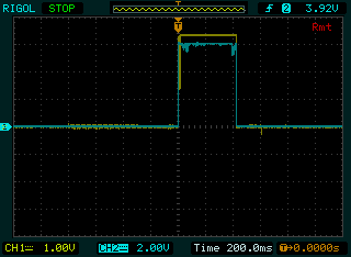
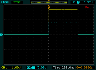
- Tested battery voltage switch circuit. Outcome shows, that it works as expected:


5.11.2017
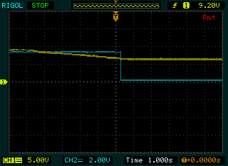
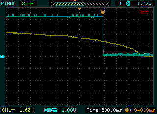
- Tested battery voltage monitor circuit and overheat monitor circuit. As designed, battery voltage monitor trips when battery voltage declines below 6.0 V. Temperature monitor circuit trips at voltage level below 1.25 V, which corresponds to 65 C for NTC thermistor integrated into thermoprinter head.


12.11.2017
- Received HC-05 Bluetooth transceivers:

- Published firmware on GitHub: https://github.com/dmmedia/Thermoprinter
- Firmware framework borrowed from Marlin 3D printers firmware.
- Conversion from AVR to STM32 and adapting for thermoprinter is in progress (removing more than 1 stepper motor support, replacing analogue sensors and replacing endstops with bistate sensors)
21.11.2017
- Received SPP-C Bluetooth transceivers
- Tested both HC-05 and SPP-C modules. HC-05 modules need to be powered on in special sequence to boot into AT command mode, while SPP-C modules are always in AT mode, while not connected to other Bluetooth device. Both modules do not require hardware flow control. Many android software applications support traditional Bluetooth serial communication.
- Firmware code is mostly ported from AVR to STM32 platform and unneeded functionality removed. At the moment ADC code left partially ported.
08.03.2018
- Counting printable bits to optimize the number of simultaneously driven 64-bit blocks turned out to be a combinatorial task or Partition problem. More specifically a Bin packing problem. Generally speaking, the resulting count of sums of simultaneously driven blocks will be not more than optimal count plus 2 if I would use First fit decreasing or Best fit decreasing algorithms.
- Counting bits themselves turned to be another well-known problem named Hamming weight. Need to check whether STM32 has any special support for bit counting.
02.04.2020
- Thought that porting Marlin 3D printer firmware was bad idea, since the functionality is totally different and Marlin implementation is not brilliant. Will start from scratch and implement stepper motor advance on user button press and hold. Motor will advance with the lowest speed described in the thermal head manual. Next step will add accelleration and deceleration.
electronics/thermoprinter.txt · Last modified: by dmmedia

